Welcome to the official website of Nesfo Valve Manufacturing (Quanzhou) Co!
Welcome to the official website of Nesfo Valve Manufacturing (Quanzhou) Co!


Addressing common technical and operational questions regarding valve selection, installation, and maintenance
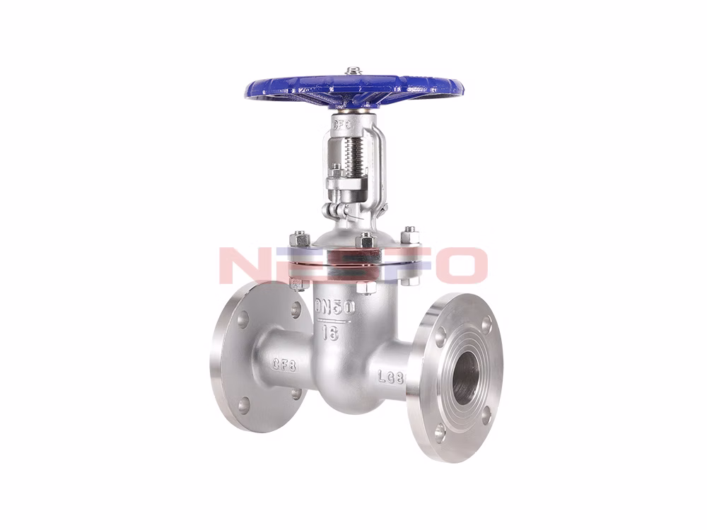
The gate valve has a double-sided forced seal:
Meaning that whether in the medium of the inlet or outlet end, the gate and seat sealing surface is sealed, sealing by the stem axial force to ensure that mandatory, when there is no medium, the positive pressure between the sealing surface shall not be less than the medium static pressure and sealing force and the sum of.
The gate valve has a one-sided forced seal:
Means in the media inlet side of the gate and the valve seat sealing surface is not sealed, here or no pressure or only than the sealing pressure for the small pressure. In the media outlet side of the sealing surface between the gate and the valve seat sealing surface is by the stem axial force and media pressure to ensure that mandatory, when there is no media, the sealing surface of the specific pressure must not be less than the sealing pressure.
(1) According to the structure of the gate plate is divided into two categories
(2) Divided into two categories according to the structure of the valve stem
Minimum stem diameter is the diameter of the portion of the stem in contact with the packing. Minimum stem diameter refers to the diameter of the stem threaded rebate groove.
The handle and handwheel are painted to represent the paint color of the sealing surface material, as detailed in the table below.
Valve handle and handwheel painted color:
Sealing surface material | Handle and handwheel paint colors | Sealing surface material | Handle and handwheel paint colors |
Bronze or Brass | red (color) | Cemented carbide | azure |
pasteurized alloy | yellow (color) | plastics | prune (color) |
铝 | aluminum white | Foundry Iron | ferrous |
Acid-resistant steel, stainless steel | light blue | caoutchouc | medium green |
nitriding steel | lilac | Monel alloy | navy blue |
The opening and closing direction of the general-purpose valve is specified as: clockwise direction is closed, counterclockwise direction is open.
The mandatory and optional symbols for general purpose valves are shown in the table below.
Valve markings:
sports event | symbolize | sports event | symbolize |
1 | Nominal Size DN (NPS) | 11 | Product standard code |
2 | Nominal pressure PN (class) | 12 | furnace number |
3 | Material designation of pressurized parts | 13 | Material designation of internal parts |
4 | Manufacturer's name or trademark | 14 | job number |
5 | Arrow for media flow direction | 15 | Lining Material Designator |
6 | Seal Ring (Gasket) Designator | 16 | Quality and test marks |
7 | Limiting temperature (°C) | 17 | Inspector's imprint |
8 | Thread code | 18 | Product Manufacturing License No. |
9 | ultimate pressure | 19 | Year and month of manufacture |
10 | Manufacturing plant number | 20 | Quality Satisfaction Level (QSL) |
Note: Nominal pressure casting on the valve body is equal to 10 times the number of megapascals (MPa), set in the nominal pressure value of the value below, the front is not crowned with the code “PN”.
Marking Methods:
(1) Nominal size greater than or equal to DN50 valve marking:
(2) Marking of valves with nominal size less than DN50:
(3) Additional signs:
For pressure reducing valves, in addition to the marking on the valve body in accordance with the general valve regulations of the 19 provisions, there should also be: the date of shipment, the applicable medium, the outlet pressure.
For the marking of steam traps in accordance with the provisions of GB/T 12250-2005, the marking can be located on the valve body, can also be marked on the label.
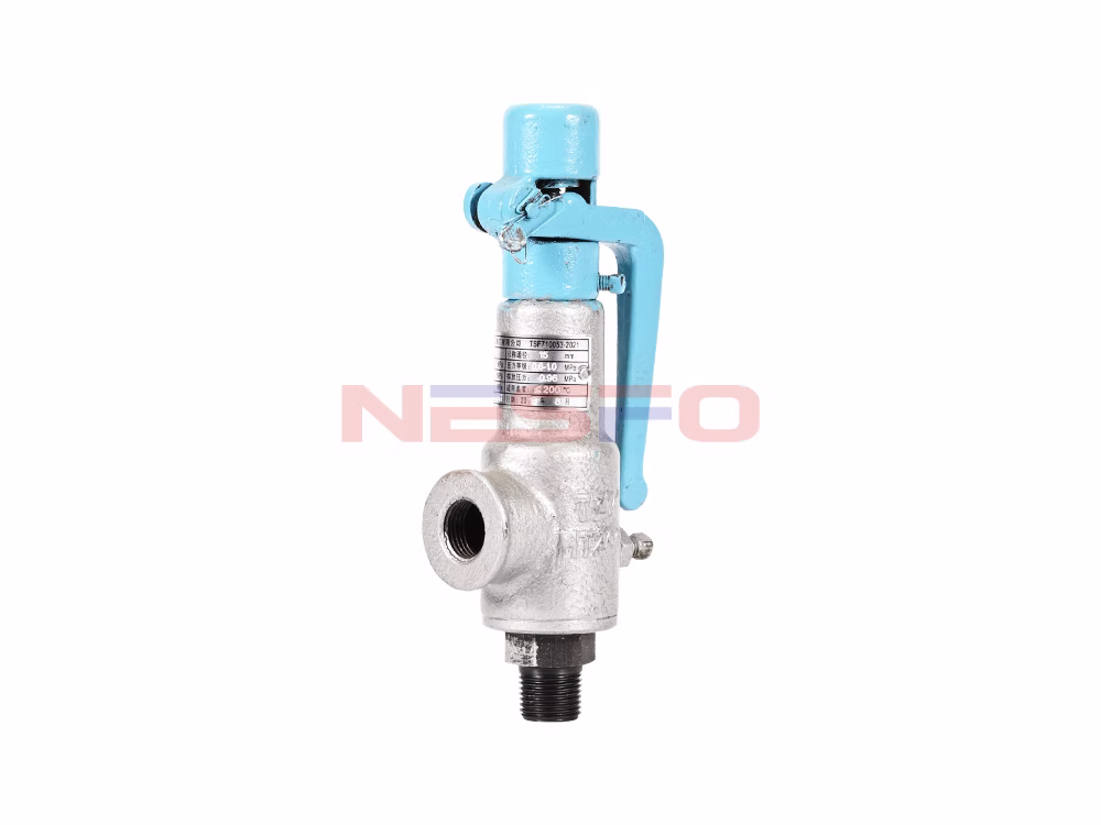
The marking of safety valves is in accordance with GB/T 12241-2005.
Ball valves, parallel gate valves, and plug valves are marked in accordance with API 6D-2014.
Sealing surface material designators machined directly from the valve body are indicated by “W”, and the remaining material designators are shown in the table below.
Seat sealing surface or lining material designator:
Seat sealing surface or lining material | nicknames | Seat sealing surface or lining material | nicknames |
Tin-based bearing alloys (pasteurized alloys) | B | Nylon Plastic | N |
enamels | C | Boron infiltrated steel | P |
nitriding steel | D | lead lining | Q |
fluoroplastic | F | austenitic stainless steel | R |
ceramics | G | plastics | S |
Cr13 stainless steel | H | copper alloy | T |
rubber lining | J | caoutchouc | X |
Monel alloy | M | Cemented carbide | Y |
Note: When the sealing surface material of the sealing pair is different, the material designation with lower hardness is used.
For gate, globe, and check valves, as well as ball and butterfly valves, the sealing specific pressure qMF must be less than the sealing specific pressure q, and the sealing specific pressure is less than the sealing allowable specific pressure [q] (i.e., qMF < q < [q]).
General-purpose valve shell test pressure for the material at 38 ℃ when the rated working pressure of 1.5 times. High-pressure sealing test for the material at 38 ℃ when the rated working pressure of 1.1 times. Low-pressure sealing test of each standard requirements are different.
Among them:
GB/T 13927-1992, ISO 5208:2008, EN 12266.2-2012 is 0.6MPa±0.01MPa;
GB/T 26481-2011, API 598-2009 is 0.4MPa~0.7Mpa;
MSS SP61-2013 is 0.56 MPa;
API 6D-2014 for Type I: 0.034MPa~0.1MPa, Type II: 0.55MPa±0.69MPa;
ISO 14313:2007 for Type I: 0.05MPa~0.1MPa, Type II: 0.55MPa±0.07MPa;
API 6A (idt ISO 10423:2003) for PSL3G: first: rated pressure, second: 2.0MPa ± 0.2MPa; PSL4: first: rated pressure, second: 2.0MPa ± 0.2MPa.
sports event | Applicable Temperature |
High temperature valve | Medium working temperature greater than 450 ℃ |
Heat-resistant valves | Medium working temperature above 600℃ |
Cryogenic valves | Medium working temperature in -29 ℃ ~ -100 ℃ |
Ultra-low temperature valve | Medium working temperature less than -100℃ |
sports event | Nominal size |
Extra large caliber valves | DN≥1400mm |
Large Caliber Valve | DN350mm~1200mm |
Medium caliber valves | DN50mm~300mm |
Small diameter valves | DN≤40mm |
sports event | Nominal Pressure |
Ultra High Pressure Valves | PN≥100MPa |
High Pressure Valves | PN10.0MPa~80.0MPa |
Medium Pressure Valves | PN2.5MPa~6.4MPa |
Low Pressure Valves | PN≤1.6MPa |
Classification of valves by purpose or main structural features.
General classification method, that is, according to the principle, role and structure, is currently the most commonly used domestic and international classification method. Generally divided into: gate valves, globe valves, plug valves, ball valves, butterfly valves, diaphragm valves, check valves, throttle valves, safety valves, pressure reducing valves, steam traps, regulating valves.
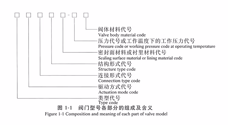
Valve model by the valve type, drive mode, connection form, structural form, sealing surface material or lining material type, pressure code or working temperature under the working pressure, valve body material and other code combination.
Valve model consists of 7 parts whose meanings are shown in the figure.
NPS:
Combined alphanumeric size designation for piping system components consisting of the letters NPS followed by a dimensionless integer number. This number is directly related to a characteristic dimension such as the bore or outside diameter of the end connection. The dimensionless number may be used as a dimensional designation for valves without the prefix “NPS”. Dimensionless size numbers do not represent measured values and cannot be used for calculations.
Class:
A combination of letters and numbers used to identify the pressure/temperature capability of a valve in relation to the mechanical and dimensional properties of the valve material. It consists of the letter Class followed by a dimensionless integer. The number following the letter Class does not represent a measured value and should not be used in calculations. The permissible pressure of piping elements depends on the Class value, the material and the permissible working temperature, unless otherwise specified in the respective standard. The permissible pressures are given in the pressure-temperature rating tables of the respective standards.
DN:
A combination of letters and numbers used to identify the size of piping system components. It consists of the letter DN followed by an integer number without a factor. This number is directly related to the characteristic dimensions of the end connection, such as the bore diameter or the outside diameter (expressed in mm).
Notes:
PN:
A combination of letters and numbers used for reference purposes in connection with the mechanical and dimensional properties of piping system components. It consists of the letter PN followed by a non-factorized number.
Notes:
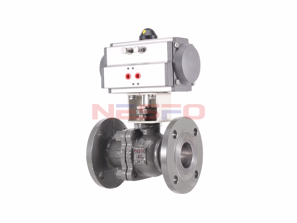
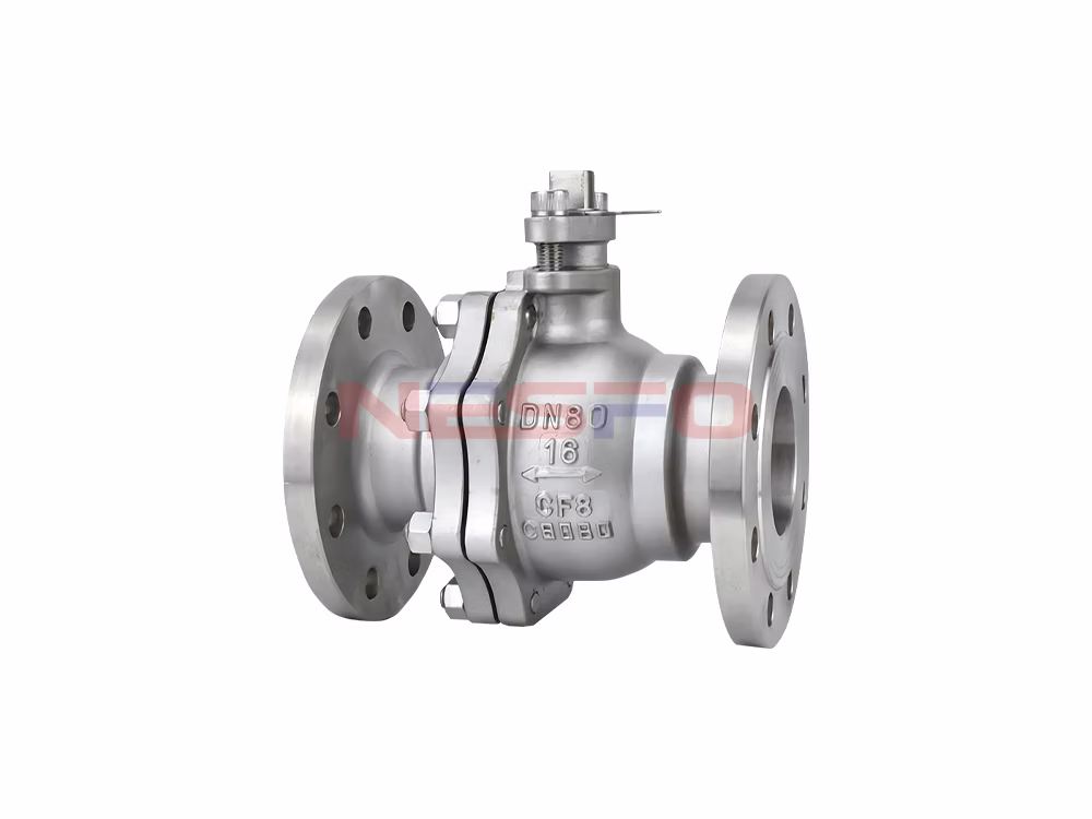
Valves commonly used in pipelines in various industrial enterprises.
Used to control the flow of media in the pipeline, with a movable mechanism of the mechanical products of the general term.
![]()
Specialized in the development and production of fluid control valves
Nesfo Valve mainly develops and manufactures:ball valves, butterfly valves, gate valves, globe valves, check valves, filters, water control valves, safety valves, pressure reducing valves, respiratory valves, regulating valves, pneumatic valves, electric valves and so on.